ESP8285 module from a Gosund WP3 smart plug
The Gosund WP3 smart plug is a Wifi-controllable relay:

Hardware
Inside, it contains an ESP8285 module labeled "T201-V1.0". The ESP8285 is a variant of ESP8266 with 1 MiB on-chip flash.
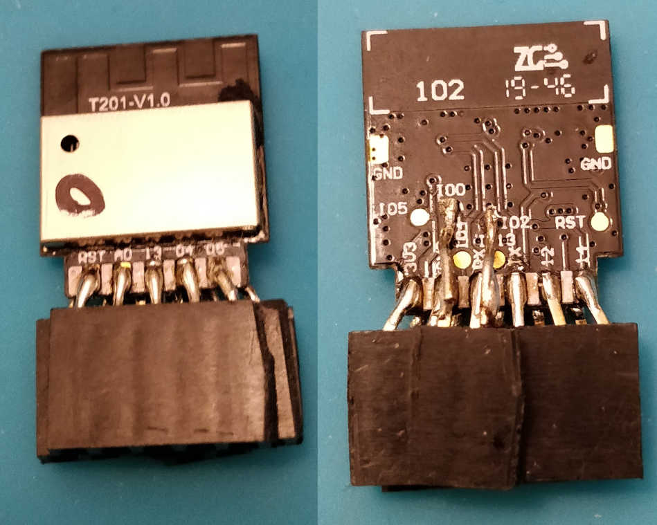
The following pins are exposed:
| Front rectangular pads | Rear rectangular pads | Rear circular pads | |||
|---|---|---|---|---|---|
| Silkscreen | Function | Silkscreen | Function | Silkscreen | Function |
| RST | EXT_RSTB | 3V3 | VDD | RST | EXT_RSTB |
| AD | ADC | GND | GND | IO0 | GPIO0 |
| 13 | GPIO13 | RX | UART Rx | IO2 | GPIO2 |
| 04 | GPIO4 | TX | UART Tx | IO4 | GPIO4 |
| 05 | GPIO5 | 12 | GPIO12 | IO5 | GPIO5 |
| 14 | GPIO14 | IO13 | GPIO13 | ||
Refer to the ESP8285 datasheet (rehosted copy) for pin descriptions.
I soldered headers to the front and rear rectangular pads as well as the two circular pads that didn't have redundant pads, IO0 and IO2.
Programming
To program, you'll need a 3.3V USB-to-serial board. I used a FTDI Basic Breakout board from SparkFun, with the jumper on the rear switched to the 3.3V setting.
Make the following connections between your ESP8285 module and the USB-to-serial board:
| Serial | ESP8285 module |
|---|---|
| GND | GND and IO0* |
| 3V3** | 3V3 |
| TXO | RX |
| RXI | TX |
| DTR | RST |
* Needed to put the module ESP8285 in programming mode.
** Labeled 5V on my board because that is its default voltage.
Plug the USB-to-serial board into your computer. Run esptool to confirm that you can make a connection:
$ esptool.py -p /dev/ttyUSB0 read_mac
esptool.py v2.8
Serial port /dev/ttyUSB0
Connecting....
Detecting chip type... ESP8266
Chip is ESP8285
Features: WiFi, Embedded Flash
Crystal is 26MHz
MAC: c4:4f:33:xx:xx:xx
Uploading stub...
Running stub...
Stub running...
MAC: c4:4f:33:xx:xx:xx
Hard resetting via RTS pin...
To back up the firmware:
$ esptool.py -p /dev/ttyUSB0 read_flash 0 0x100000 fwbackup.bin
esptool.py v2.8
Serial port /dev/ttyUSB0
Connecting.....
Detecting chip type... ESP8266
Chip is ESP8285
Features: WiFi, Embedded Flash
Crystal is 26MHz
MAC: c4:4f:33:xx:xx:xx
Uploading stub...
Running stub...
Stub running...
1048576 (100 %)
1048576 (100 %)
Read 1048576 bytes at 0x0 in 99.0 seconds (84.7 kbit/s)...
Hard resetting via RTS pin...
Unfortunately, I did not back up my firmware before flashing it, so I don't have a copy of the Gosund WP3 firmware.
To flash a new program to the chip, such as Tasmota, do the following:
$ wget https://github.com/arendst/Tasmota/releases/download/v8.4.0/tasmota.bin
$ esptool.py -p /dev/ttyUSB0 write_flash -fs 1MB -fm dout 0 tasmota.bin
esptool.py v2.8
Serial port /dev/ttyUSB0
Connecting.....
Detecting chip type... ESP8266
Chip is ESP8285
Features: WiFi, Embedded Flash
Crystal is 26MHz
MAC: c4:4f:33:xx:xx:xx
Uploading stub...
Running stub...
Stub running...
Configuring flash size...
Compressed 606368 bytes to 427780...
Wrote 606368 bytes (427780 compressed) at 0x00000000 in 38.0 seconds (effective 127.7 kbit/s)...
Hash of data verified.

Leaving...
Hard resetting via RTS pin...
The -fs 1MB is there because the ESP8285 has 1 MiB of flash. The -fm argument is described on the esptool documentation.
To boot into the program you flashed:
- Disconnect the USB cable
- Unplug IO0 to take the chip out of programming mode
- Connect RST to 3.3V
- Reconnect the USB cable
If you flashed Tasmota, you should be able to connect with picocom or any other serial terminal. Issue the status command to see the current status:
$ picocom --baud 115200 --echo --omap crcrlf /dev/ttyUSB0
picocom v3.1

port is        : /dev/ttyUSB0
flowcontrol    : none
baudrate is    : 115200
parity is      : none
databits are   : 8
stopbits are   : 1
escape is      : C-a
local echo is  : yes
noinit is      : no
noreset is     : no
hangup is      : no
nolock is      : no
send_cmd is    : sz -vv
receive_cmd is : rz -vv -E
imap is        :
omap is        : crcrlf,
emap is        : crcrlf,delbs,
logfile is     : none
initstring     : none
exit_after is  : not set
exit is        : no

Type [C-a] [C-h] to see available commands
Terminal ready
status
08:40:52 CMD: status
08:40:52 RSL: stat/tasmota_XXXXXX/STATUS = {"Status":{"Module":1,"DeviceName":"Tasmota","FriendlyName":["Tasmota"],"Topic":"tasmota_XXXXXX","ButtonTopic":"0","Power":0,"PowerOnState":3,"LedState":1,"LedMask":"FFFF","SaveData":1,"SaveState":1,"SwitchTopic":"0","SwitchMode":[0,0,0,0,0,0,0,0],"ButtonRetain":0,"SwitchRetain":0,"SensorRetain":0,"PowerRetain":0}}
You can also access Tasmota's web UI via the tasmota_XXXXXX-XXXX Wifi network. More instructions specific to Tasmota can be found in their documentation.